

Having trouble understanding the cumbersome and lengthy installation and setup guides provided by HP when it comes to setting up and deploying an HP MSM controller-based wireless solution? Take a look at this how-to document written by Source One Technology to help you better understand the necessary steps for successfully deploying an HP MSM wireless controller and HP wireless access points in your network environment.
In this article we explain everything from the design phase of planning of your routing, switching, and network VLANs, all the way up to the final configuration touches on your wireless controller that will provide you with a fully robust and seamless wireless solution! Configuring an HP wireless solution has never been so easy!
This Step by Step Walkthrough is not official HP documentation. It is meant solely to help customers better understand the steps involved in an HP MSM wireless deployment. The HP MSM product can be configured numerous ways for different scenarios, this is but one example.
Guide Revision: 0.4H

This Wisconsin manufacturer needed to modernize its IT infrastructure to support rapid business growth.
Discover what they did1. Background information
Current network layout
Customer wants to deploy an HP wireless infrastructure to meet their growing wireless needs. The network infrastructure currently consists of an HP 5406ZL core chassis and two HP E2520G-POE-24 switches. Currently there are 3 VLANs implemented for various purposes and management. The servers and network infrastructure are located on VLAN 1, wired computers are located on VLAN 130, and IP Phones are located on VLAN 140.
The following diagram (Figure 1) depicts the current network topology layout.
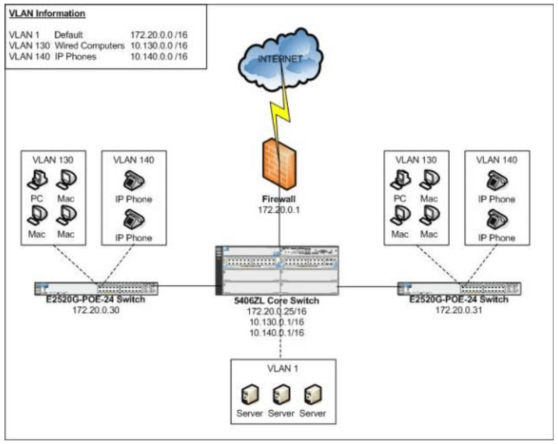
Figure 1
Proposed network layout (with HP MSM wireless)
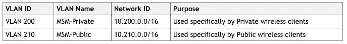
With the addition of an HP MSM wireless network, the customer wants to provide two different wireless networks: a Private wireless network, and a Public wireless network. The following highlights the design goals for each particular wireless network that will be implemented:
Private wireless
- Allow only company-owned, or IT-managed, devices on the Private wireless network.
- Use WPA2-PSK security for data encryption.
- Enable Broadcast Filtering to improve wireless performance and reduce unnecessary wireless traffic.
- Enable Band Steering so dual-band capable clients are directed to the 5GHz radios instead of 2.4GHz radios.
- Allow communication between wireless client devices.
- IP addresses for wireless clients are issued by a local Windows DHCP server.
Public wireless
- Allow any wireless device on the Public wireless network.
- No data encryption – for easier client configuration.
- Prevent guest users from accessing ANY network resources – ONLY allow direct internet access.
- Enable a splash page that forces guest users to authenticate before given access to browse the internet.
- Enable Broadcast Filtering to improve wireless performance and reduce unnecessary wireless traffic.
- Prevent all communication between wireless devices.
- IP addresses for wireless clients are issued by the DHCP Server on the MSM 760 controller.
To accommodate the goals of the two additional wireless networks, two additional VLANs will need to be created in the current network infrastructure.
The following diagram (Figure 2) depicts the proposed network topology layout and changes.
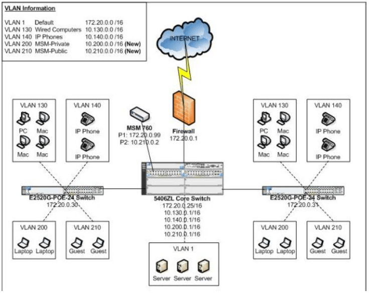
Figure 2
Several changes, including IP addressing and VLAN information will need to be implemented at the core HP 5406ZL switch and at the various HP E2520G edge switches to accommodate the proposed wireless network changes. The changes can be put in place with causing any disruption or outages to the network.
2. Switch configuration changes
Core switch configuration
The 5406ZL core switch will need to have the following configuration changes made to accommodate the new MSM wireless deployment:
- Creation of VLAN 200 and VLAN 210.
- Add IP addresses assigned to VLAN 200 and VLAN 210 for routing purposes.
- Add Proper VLAN tagging for the uplink ports between the 5406ZL Core and edge E2520G-POE-24 switches.
- Add Proper VLAN tagging for the MSM 760 controller’s Internet and LAN Ports.
When complete, your configuration of the core switch should reflect the configuration shown in Figure 3 below.
Create VLAN 200 and VLAN 210 and Assign IPs on the Core switch
- Access the switch via a console port cable, telnet, or SSH connection as applicable.
- Provide applicable login credentials.
- Enter the Command Line (CLI) interface of the switch.
- Type “config” at the prompt to enter Configuration Mode.
- Type “vlan 200 name MSM-Private” to create the VLAN used by the Private wireless.
- Type “vlan 200 ip address 10.200.0.1 255.255.0.0” to set the IP address for VLAN 200.
- Type “vlan 210 name MSM-Public” to create the VLAN used by the Public wireless.
- Type “vlan 210 ip address 10.210.0.1 255.255.0.0” to set the IP address for VLAN 210.
- Type “write mem” to save the switch configuration.
Configure the Uplink ports (Port B23 and B24) on the Core switch to the Edge switches
- Access the switch via a console port cable, telnet, or SSH connection as applicable.
- Provide applicable login credentials.
- Enter the Command Line (CLI) interface of the switch.
- Port B23 is the uplink port to the 172.20.0.30 (E2520G-POE-24) switch – set applicable VLAN tagging for the newly created VLAN 200 and VLAN 210.
- Type “config” at the prompt to enter Configuration Mode.
- Type “vlan 200 tagged b23”.
- Type “vlan 210 tagged b23”.
- Port B24 is the uplink port to the 172.20.0.31 (E2520G-POE-24) switch – set applicable VLAN tagging for the newly created VLAN 200 and VLAN 210.
- Type “vlan 200 tagged b24”.
- Type “vlan 210 tagged b24”.
- Type “write mem” to save the switch configuration.
Configure the MSM 760 LAN Port and Internet Ports (A1 and A2) on the Core switch
- Access the switch via a console port cable, telnet, or SSH connection as applicable.
- Provide applicable login credentials.
- Enter the Command Line (CLI) interface of the switch.
- Type “config” at the prompt to enter Configuration Mode.
- Type “vlan 210 untagged a1”
- Type “vlan 1 untagged a2”
- Type “write mem” to save the switch configuration.
Edge switches configuration
The two HP E2520G-POE-24 switches shown in Figure 2 will need to have the following configuration changes made to accommodate the new MSM wireless deployment:
- Creation of VLAN 200 and VLAN 210
- Proper VLAN tagging for Port 24 (the Uplink port to the 5406ZL core switch)
- Proper VLAN tagging for Ports 1-10 (the ports used by the MSM 460 Access Points)
When complete, your configuration of the Edge switches should reflect the configuration show in Figure 3 below.
Create VLAN 200 and VLAN 210 on both Edge switches
- Access the switch via a console port cable, telnet, or SSH connection as applicable.
- Provide applicable login credentials.
- Enter the Command Line (CLI) interface of the switch.
- Type “config” at the prompt to enter Configuration Mode.
- Type “vlan 200 name MSM-Private” to create the VLAN used by the Private wireless.
- Type “vlan 210 name MSM-Public” to create the VLAN used by the Public wireless.
Configure the Uplink ports (Port 24) on both Edge switches to the 5406ZL Core switch
- Access the switch via a console port cable, telnet, or SSH connection as applicable.
- Provide applicable login credentials
- Enter the Command Line (CLI) interface of the switch.
- Type “config” at the prompt to enter Configuration Mode.
- Type “vlan 200 tagged 24” to tag Uplink Port 24 for VLAN 200 traffic.
- Type “vlan 210 tagged 24” to tag Uplink Port 24 for VLAN 210 traffic.
When VLAN tagging for the switches and uplink ports are complete, your switch configuration should resemble this diagram (see Figure 3).
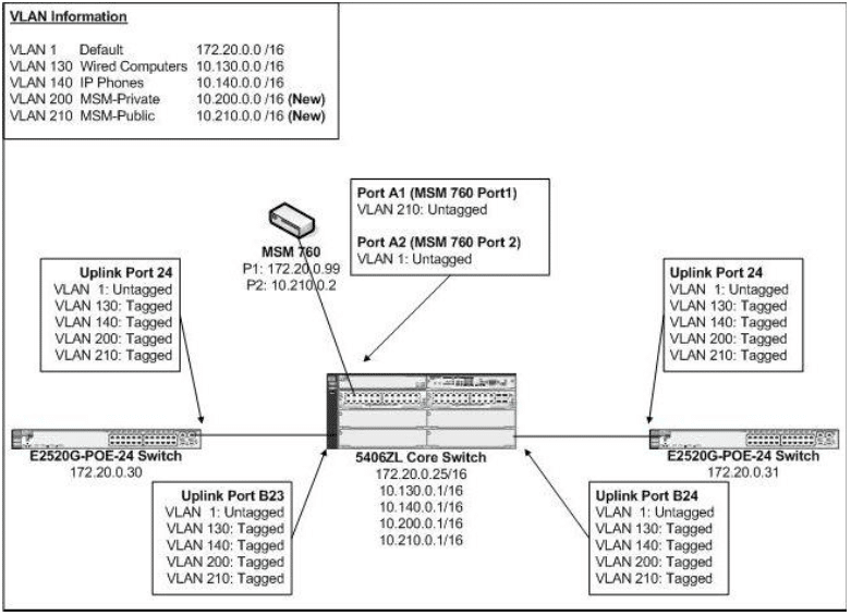
Figure 3
Configure the Edge ports on both Edge switches for the MSM 460 APs (Ports 1-10)
Each Edge switch will have MSM 460 APs directly connected on ports 1-10. AP’s will be configured for VLANs in the following manner:
- Untagged on VLAN 1 – for purposes of receiving an IP address and management.
- Tagged on VLAN 200 – for purposes of the Private VSC
- Tagged on VLAN 210 – for purposes of the Public VSC
- Access the switch via a console port cable, telnet, or SSH connection as applicable.
- Provide applicable login credentials.
- Enter the Command Line (CLI) interface of the switch.
- Type “config” at the prompt to enter Configuration Mode.
- Type “vlan 1 untagged 1-10” to untag ports designated for MSM 460 APs on VLAN 1.
- Type “vlan 200 tagged 1-10” to tag ports designated for MSM 460 APs on VLAN 200.
- Type “vlan 210 tagged 1-10” to tag ports designated for MSM 460 APs on VLAN 210.
Type “show vlan 200” on both Edge switches and verify you see the following configuration as shown in Figure 4:
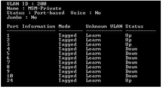
Figure 4
Type “show vlan 210” on both Edge switches and verify you see the following configuration as shown in Figure 5:
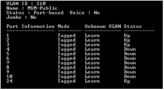
Figure 5
Also verify that the edge ports used for the MSM APs and the uplink ports are also untagged for VLAN 1 (the Default VLAN) as shown in Figure 3. When complete, type “write mem” to save the switch configuration on both Edge switches.
3. DHCP setup
DHCP server setup – scope creation and IP helpers
The Private wireless VSC will be egressed to the network on VLAN200. We will need to make the following configuration changes in order to allow wireless clients connected to the Private wireless VSC to receive an IP address from the local Windows Server:
- Configure an IP Helper address for VLAN 200 on the core 5406ZL switch
- Create a DHCP Scope for VLAN 200 on the local Windows Server
Configure the appropriate IP helper address
- Access the 5406ZL core switch via a console port cable, telnet, or SSH connection as applicable.
- Provide applicable login credentials.
- Enter the Command Line (CLI) interface of the switch.
- Type “config” at the prompt to enter Configuration Mode.
- Type “vlan 200 ip helper-address 172.20.100.23” (our local Windows Server hosting DHCP).
- Type “write mem” to save the switch configuration.
VLAN 200 should now show the following IP Helper information when issuing a “show run” command on the core 5406ZL switch (see Figure 6)
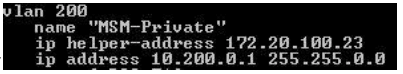
Figure 6
Create the DHCP scope for VLAN 200 on the Windows Server
- Logon to the local Windows Server (172.20.100.23 in this scenario) and start the DHCP management console application from Administrative Tools.
- Expand DHCP -> Your Server -> IPv4 and select New Scope from the Action toolbar menu.
- Assign a name to the Scope (for example, MSM-Private).
- Enter the appropriate range of IP addresses.
- Starting address 10.200.1.0
- Ending address 10.200.9.255
- Subnet Mask 255.255.0.0
- No IP exclusions are necessary as part of this scenario.
- Set a lease duration of 8 hours.
- When asked to configure scope option now, choose Yes.
- Default gateway – 10.200.0.1 (the 5406ZL core switch)
- Parent domain – mycompany.local
- DNS Server – 172.20.100.23 (the local Windows DNS server)
- Activate the DHCP Scope and click Finish when completing the wizard
4. MSM 760 Controller – initial setup
Initial setup
Start by setting up the basic one-time configuration options that require input the first time you log on to the MSM 760 controller. It would also be advisable to update to the latest version of production firmware code that is available through HP Procurve Support services.
- Change your PC’s network card IP from DHCP to a Static IP address of 192.168.1.50 with a 255.255.255.0 Subnet Mask.
- Physically connect your PC’s network card to Port 2 (LAN Port) of the MSM 760 controller.
- Access the MSM 760 controller via a web browser at address https://192.168.1.1
- Login using the default username of admin and password of admin.
- Agree to the HP End User License Agreement.
- When asked to Register, select the Register Later option.
- Select the appropriate Country Code and click Save.
- Change the default administrator password from admin to your preference and click Save.
- Update the firmware to the latest production release.
- From the main interface menu, select Controller ->Maintenance -> Firmware updates.
- Click Browse and select the applicable firmware release.
- Click Install to install the firmware.
- Wait for MSM 760 to install firmware and reboot the controller.
- Connect to the MSM 760 controller via a web browsing at address https://192.168.1.1
- Login using applicable username and password that was set in earlier steps.
IP configuration
The next step is to configure both the LAN and Internet Ports of the MSM 760 controller for proper IP address as we defined earlier in our wireless deployment scenario (see Figure 2) and plugging in the LAN Port and Internet Port to the Core 5406ZL switch.
- Connect to the MSM 760 controller via a web browsing at address https://192.168.1.1
- Login using applicable username and password that was set in earlier steps
- Setup the LAN Port IP address (172.20.0.99)
- From the main interface menu, select Controller -> Network -> Ports
- Click LAN Port – Set IP address to 172.20.0.99 with a Subnet Mask of 255.255.0.0 then click Save. (At this time, your PC will lose access to the controller because of the IP/network change)
- Disconnect your PC from Port 2 (LAN Port) of the MSM 760 controller.
- Change your PC’s network card from the previously assigned Static IP address of 192.168.1.50 to a DHCP address.
- Connect your PC’s network card to the network on VLAN 1.
- Verify your PC is given a DHCP address on VLAN 1 from your local DHCP server.
- Connect port 2 (LAN Port) of the MSM 760 controller to port A2 of the Core 5406ZL switch.
- Ping the LAN Port of the MSM 760 controller (172.20.0.99) to verify connectivity.
- Access the MSM 760 controller via a web browser at address https://172.20.0.99
- Login using applicable username and password that was set in earlier steps.
- Setup the Internet Port IP address (10.210.0.2)
- From the main interface menu, select Controller -> Network -> Ports
- Click Internet Port – Change from DHCP Client to Static, and then click on Configure.
- Specify IP address as specified earlier, 10.210.0.2 with Subnet Mask of 255.255.0.0 and click Save, and then click Save again, to return to the Port Configuration page (see Figure 6).
- Connect port 1 (Internet port) of the MSM 760 controller to port A1 of the Core 5406ZL switch.
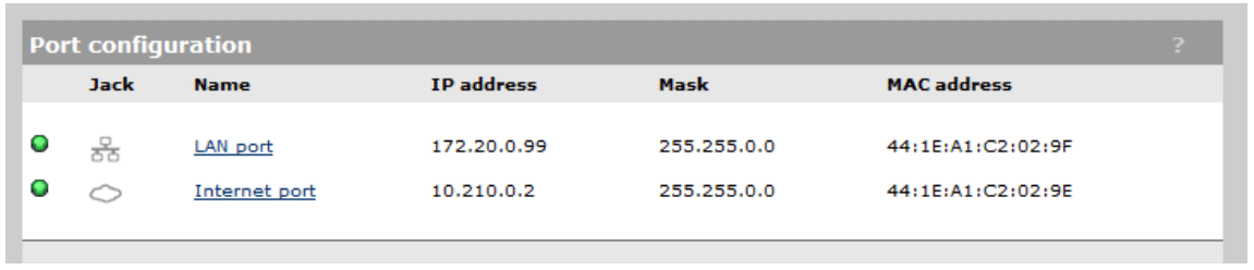
Figure 6
V. MSM 760 Controller – configuration
Setup DNS
Proper DNS Server configuration is needed for successful deployment of our future Public wireless network.
- From the main interface menu, select Controller -> Network -> DNS
- Specify the DNS servers on the network, in this case we will use two Microsoft AD DNS servers.
- Server 1: 172.20.100.22
- Server 2: 172.20.100.23
- Specific DNS advanced settings.
- DNS Cache – Enable
- DNS Switch Over – Enable
- DNS Interception – Enable
- Click Save.
Your DNS information should be defined as follows (see Figure 7):
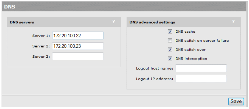
Figure 7
Setup IP routing
In our scenario, we need to setup a Default Gateway route on the MSM 760 controller so data can be sent across the various networks defined when we documented our wireless deployment.
- From the main interface menu, select Controller -> Network -> IP Routes
- Add a default route of 10.210.0.1 (IP address of VLAN 210 on the 5406ZL Core) with metric 1 and click Add.
Note — Until the Default route is added, you will not be able ping the Internet Port’s IP address from any network except the 172.20.0.0/16 and 10.210.0.0/16 networks. After the Default route has been added, you should be able to ping the Internet Port’s IP address from any network.
Your IP and Routing information should be defined as follows (see Figure 8):
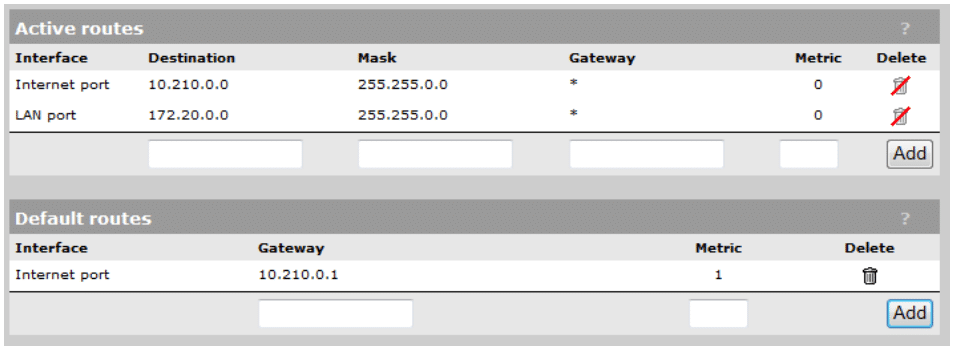
Figure 8
Address allocation and DHCP services
Because we will be using the MSM 760 controller to hand out DHCP addresses to wireless clients on the Public VSC, we need to activate the DHCP services on the controller.
- From the main interface menu, select Controller -> Network -> Address Allocation
- Change DHCP services option to DHCP Server and click Configure.
- Enter a domain name, such as “mycompany.local”.
- Change the lease time duration to 1500 seconds (or to custom value you prefer).
- Set the Listen for DHCP requests on:
- LAN Port – Disabled (You must disable this if you already have a DHCP server on the LAN Port network)
- Client data tunnel – Enabled
Your DHCP Services information should be defined as follows (see Figure 9):
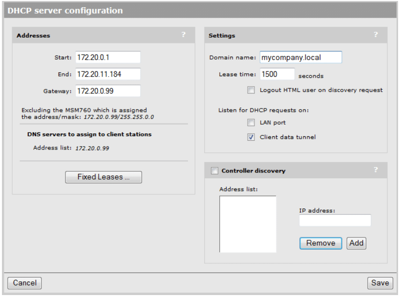
Figure 9
Remote logging
If you wish to define a remote Syslog server for logging purposes you can define this in the MSM 760 controller. Setting up a remote Syslog server will allow you to maintain a much longer retention period for various warnings, errors, and other event log entries.
- From the main interface menu, select Controller -> Tools -> Remote Log
- Specify a name for the Remote Syslog server.
- Specify the Syslog Server address. In this case we will use a Syslog server which is already setup on IP address 172.20.100.54.
- Specific the Filter definitions. Enable the checkbox next to Severity Level option and set for Higher or Equal to:
- Warning – for basic logging
- Debug – for detailed logging when you are actively troubleshooting a support issue.
- Click Save.
Your Remote Logging information should be defined as follows (see Figure 10):
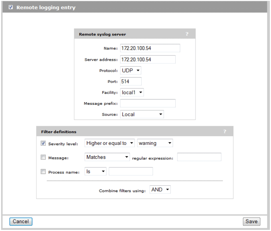
Figure 10
SNMP configuration
If you wish to monitor the MSM 760 controller via SNMP management, you can define these settings.
- From the main interface menu, select Controller -> Management -> SNMP
- Enter in the applicable information for Location and Contact attributes.
- Select your SNMP protocol versions (Version 1 and 2C are selected by default)
- Specify the applicable Community Names used for SNMP monitoring in your network.
- Specify the Notification Receiver for SNMP trap notification.
- Click Save when completed.
Time configuration
Setting the appropriate system time is important for reviewing Event Logs on the MSM 760 controller to aid in various troubleshooting steps and procedures. An external NTP server, or an internal NTP server, can be used. In this scenario we will specify the internal Domain Controller servers on the local network to be used for time synchronization.
- From the main interface menu, select Controller -> Management -> System Time.
- Change the Time Zone to the appropriate value.
- Remove any previous Time Server entries.
- Add 172.20.100.22 and 172.20.100.23 as our local Time Servers.
Your Time Configuration should be defined as follows (see Figure 11):
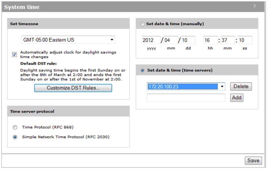
Figure 11
Bandwidth control
In some scenarios, we may want to limit the data rate of the Public wireless traffic that will be tunneled through the controller’s Client Data Tunnel and Internet Port. In this deployment scenario, our internet pipe is 75Mb, so we will set a limitation of 20Mb for all Public wireless traffic to the internet so Public wireless traffic doesn’t saturate our internet bandwidth.
- From the main interface menu, select Controller -> Network -> Bandwidth Control
- Enable the checkbox for Internet port data rate limits.
- Specify a maximum transmit and receive rate for 20480 kbps.
- Click Save.
Your Bandwidth Control should be defined as follows (see Figure 12):
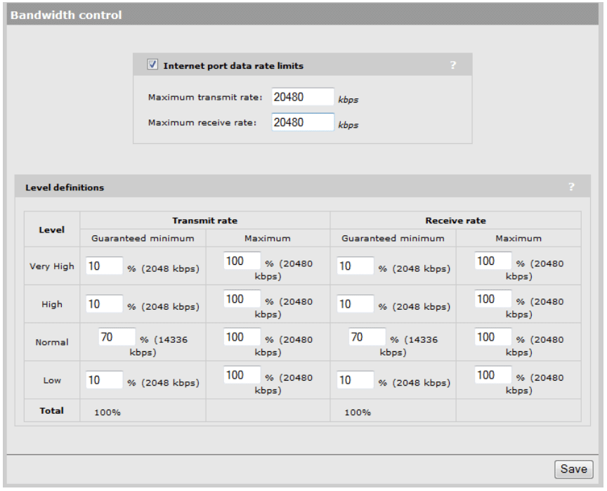
Figure 12
5. VSC setup
VSC creation – Private wireless
The goals for the Private wireless VSC were determined to be as follows:
- Allow only company-owned, or IT-managed, devices on the Private wireless network.
- Use WPA2-PSK security for data encryption.
- Enable Broadcast Filtering to improve wireless performance and reduce unnecessary wireless traffic.
- Enable Band Steering so dual-band clients are directed to the 5GHz radios instead of 2.4GHz radios.
- Allow communication between wireless client devices.
To configure the Private wireless VSC, perform the following steps:
- From the main interface menu, select Controller -> VSCs -> HP (this is the default VSC which we will edit)
- Change the Profile name from HP to Private.
- Uncheck the Authentication and Access Control check boxes.
- Change the SSID name from HP to Private.
- Enable the Broadcast Filtering check box.
- Disable the Wireless Security Filters checkbox.
- Enable wireless protection modes:
- Set Mode as WPA2 (AES/CCMP).
- Set Key Source as Preshared Key.
- Define a Key password.
- Confirm the Key password.
- Click the Save button.
Your Private VSC should be defined as follows (see Figure 13):
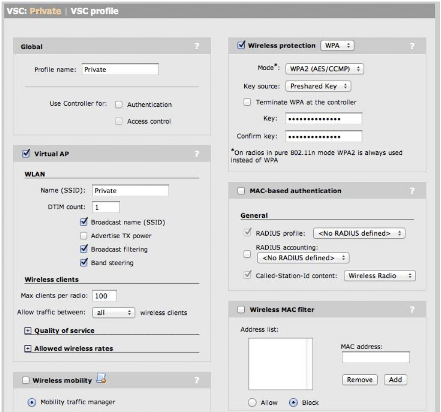
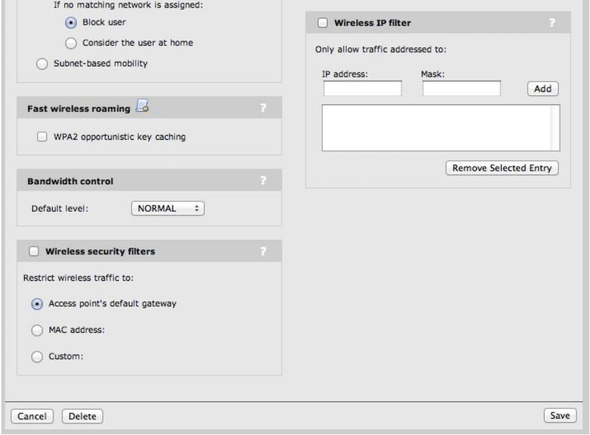
Figure 13
VSC creation – Public wireless
The goals for the Public wireless VSC were determined to be as follows:
- No wireless encryption so any guest device can connect.
- Enable a splash page redirection that forces guest users to provide authentication credentials before being allowed to browse the internet.
- Prevent guest users from accessing any network resources – only allow them access directly to the internet (this will be accomplished later through the use of setting up Access Lists in the MSM 760 controller)
- Enable Broadcast Filtering to improve wireless performance and reduce unnecessary wireless traffic.
- Prevent any client-to-client wireless traffic so users cannot access other devices on the Public network.
- Allow the MSM 760 Controller to hand out IP addresses via DHCP to Public wireless users
To configure the Public wireless VSC, perform the following steps:
- From the main interface menu, select Controller -> VSCs
- Click Add New VSC Profile
- Change the Profile name from HP to Public.
- Leave the Authentication and Access Control check boxes enabled.
- Change the SSID name from HP to Public.
- Enable the Broadcast Filtering check box.
- Change ‘Allow Traffic Between [All|No] Wireless Clients’ to No.
- Expand Client Data Tunnel and enable the ‘Always Tunnel Client Traffic’ check box.
- Disable any Wireless Protection is used (WPA/WEP) so the VSC is Open.
- Verify HTML-based User logins is enabled using Local authentication (note – we will create a guest user later in this document).
- Enable the DHCP Server option in the VSC. This will allow the MSM 760 controller to hand out DHCP addresses to the Public wireless clients in a NAT’d IP range. Set the following DHCP Server options:
- DNS – 10.220.0.1
- Start – 10.220.0.100
- End – 10.220.9.255
- Gateway – 10.220.0.1
- Netmask – 255.255.0.0
- Subnet – 10.220.0.0
- Save VSC Settings.
Your Public VSC should be defined as follows (see Figure 14):
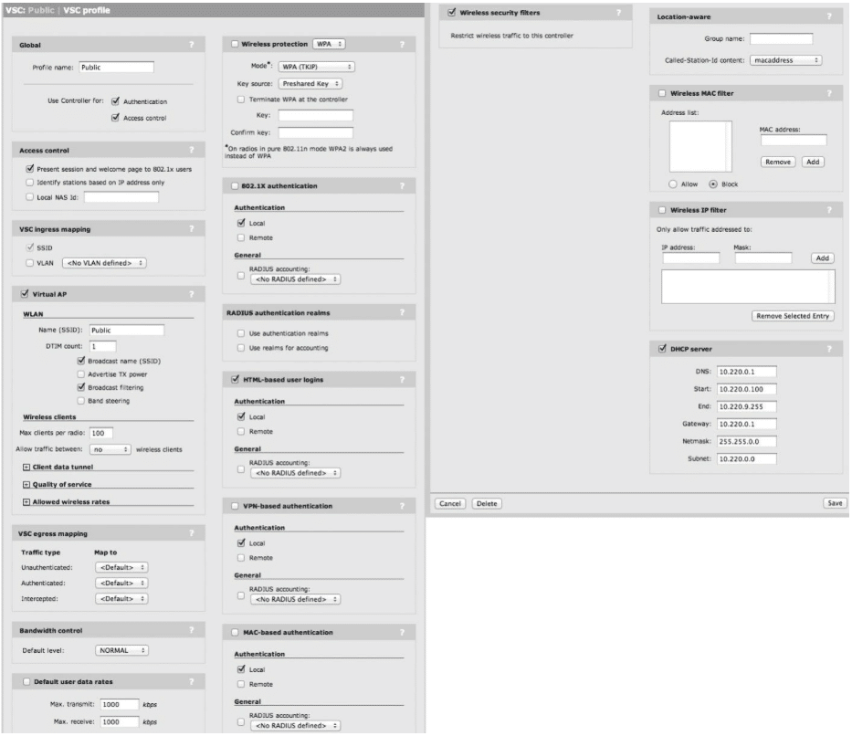
Figure 14
6. Network Profiles and VSC Bindings
Network Profiles
Now that our VSC’ have been created, we will define the Network Profiles. Our wireless deployment scenario called for setting up two different VSCs (Private and Public), each configured on their own independent VLAN.
- From the main interface menu, select Controller -> Network -> Network Profiles
- Create the Network Profile to be used for the Private VSC
- Click on Add New profile.
- Specify the name as Private.
- Enable the VLAN check box and specify the VLAN ID as 200.
- Click Save.
- Create the Network Profile to be used for the Public VSC
- Click on Add New Profile.
- Specify the name as Public.
- Enable the VLAN check box and specify the VLAN ID as 210.
- Click Save.
Your Network Profiles should now be defined as follows (see Figure 15):
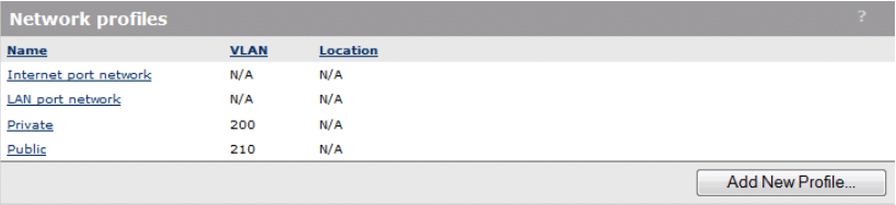
Figure 15
We will use these Network Profiles as we bind the Private VSC and Public VSC to the Default Group for our APs.
Default Group Binding
We are now ready to bind our newly created VSCs to the Default AP Group where our MSM 460 APs are located by default. To bind the VSCs to the Default AP Group, perform the following steps:
-
- From the main interface menu, expand Controller -> Controlled APs -> Default Group
- Click on VSC Bindings
- Create VSC Binding for the Private VSC
- Click Add New Binding
- Select the previously created VSC Profile “Private”
- Enable the Egress Network checkbox and select the Network Profile “Private”
- We will broadcast the Private VSC on both radios, 2.4Ghz and 5Ghz, so leave the Dual Radio Behavior at the default setting.
- Click Save
- Create the VSC Binding for the Public VSC
- Click Add New Binding
- Select the previously created VSC Profile “Public”
- Enable the Egress Network checkbox and select the Network Profile “Public”
- We will broadcast the Private VSC on both radios, 2.4Ghz and 5Ghz, so leave the Dual Radio Behavior at the default setting.
- Click Save
Your VSC Bindings to the Default AP Group should be defined as follows (see Figure 16):
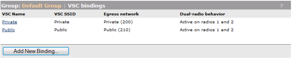
Figure 16
7. MSM 460 AP defaults – configuration
MSM 460 radio settings
This wireless AP rollout was designed in this scenario for capacity, as opposed to coverage. With that in mind, we will make several adjustments to the default radio configuration of the MSM 460s in an effort to reduce potential RF problems with channel overlap and signal saturation. The following MSM 460 radio configuration changes will be applied to the “Controlled APs” group, which all other AP groups, including the Default Group, inherit their settings from by default.
- Specify Radio 1 and Radio 2 auto-channel selection to occur once/day at 02:00 hours
- Exclude all Radio 2 channels except 1, 6, and 11 to minimize co-channel interference
- Set the maximum number of clients that can connect to a given radio at 75 for each radio
- Set the Distance Between APs value to Small for each radios as we have a rather dense AP rollout
- Change the power output for each radio from Maximum Power (100%) to 25% power
To implement these configuration changes, perform the following steps:
- From the main interface menu, expand Controller -> Controlled APs -> Configuration -> Radio List and click on E-MSM460
- Make the following changes on Radio 1 (5GHz Radio)
- Change Time Interval to Time of Day at 02:00 hours
- Set Max clients to 75
- Change Distance Between APs to Small
- Select the “Set power to” radio button and specific 25% of max power
- Make the following changes on Radio 2 (2.4GHz Radio)
- Change Time Interval to Time of Day at 02:00 hours
- Select channels 2, 3, 4, 5, 7, 8, 9, 10 (using ctrl-click) in the Automatic Channel Exclusion List settings
- Set Max clients to 75
- Change Distance Between APs to Small
- Select the “Set power to” radio button and enter 14 dBm (25% power)
- Click Save
Your E-MSM460 Radio Configuration settings should be defined as follows (see Figure 17):
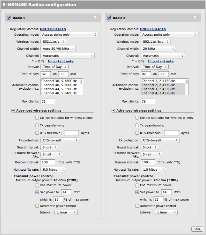
Figure 17
8. Public wireless – creating User Accounts
Creating Users Accounts for use on the Public VSC wireless network
During the creation of our Public VSC, we enabled “HTML-based User Logins” so any guest users connecting to the Public VSC will be redirected to a splash page requiring logon credentials before they can access the internet. We need to define those user accounts now. In this particular scenario, we will create a single user account called “guest” that is will be shared by all users connecting to the Public VSC. To create the “guest” user account on the MSM 760 controller, perform the following steps:
- From the main interface menu, click Users -> User Accounts
- Click Add New Account
- Specify the User Name as “guest”
- Specify the Password and Confirm Password as “guest1”
- Since this is a shared account used by than one concurrent guest user, change the Max Concurrent Sessions to 255.
- Enable the VSC Usage checkbox and restrict this account to the Public VSC only by selecting Public and clicking the right arrow button.
- Verify your User Account settings reflect the following settings (see Figure 18).
- Click Save.
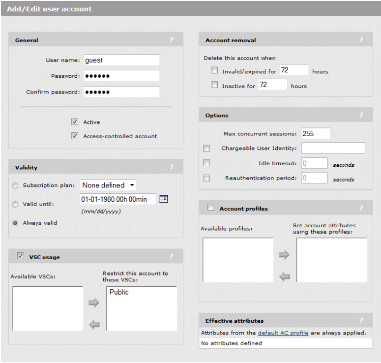
Figure 18
This “guest” user account can now be used to authenticate guest users connected to the Public VSC. Guest users will be automatically redirected to the splash page and required to enter the proper credentials before receiving internet access.
9. Public wireless – setup Access Control Lists
Create ACLs to limit access from the Public VSC to only specific network resources
With the creation of the Public VSC and creation of a “guest” user account, users with the appropriate logon information will be connected to the Public VSC after successfully authenticating on the HTML login redirect page. Since we specified the Public VSC to enforce the use of the Client Data Tunnel all traffic on the Public VSC will be tunneled through the controller. It is important we ensure that guest wireless users are prevented from accessing the production network and all related network resources. We will use the MSM 760 controller’s built-in ACL functionality to provide the following goals and restrictions for all guest wireless traffic.
- Allow the “guest” account direct access to the Internet
- Allow the “guest” account access to the company’s internal Web Server (172.20.100.50) on port 80
- Allow the “guest account access to the company’s internal Web Server (172.20.100.50) on port 443
- Deny the “guest” account access to ALL other production network and network resources
To achieve the goals mentioned above, perform the following steps for creating the ACLs:
- From the main interface menu, click Public Access -> Attributes
- Click Add New Attribute
- Select Default-User-Use-Access-List from the dropdown box and specify a value of Public (this will assign an access list called Public to ALL users authenticated by the MSM 760 Controller, including the “guest” account we created earlier and any new accounts we might create in the future).
- Click Add.
- Click Add New Attribute
- Verify Access-List is selected in the Name dropdown box.
- Type “public,accept,tcp,172.20.100.50/32,80” (allow HTTP traffic to company’s internal web server).
- Click Add.
- Click Add New Attribute
- Verify Access-list is selected in the Name dropdown box.
- Type “public,accept,tcp,172.20.100.50/32,443” (allow SSL traffic to company’s internal web server).
- Click Add.
- Click Add New Attribute
- Verify Access-list is selected in the Name dropdown box.
- Type “public,deny,all,172.0.0.0/8,all” (block all traffic from the Public VSC to network resources).
- Click Add.
- Click Add New Attribute
- Verify Access-list is selected in the Name dropdown box.
- Type “public,deny,all,10.0.0.0/8,all” (block all traffic from the Public VSC to network resources).
- Click Add.
- Click Add New Attribute
- Verify Access-list is selected in the Name dropdown box.
- Type “public,accept,all,all,all” (allow all remaining traffic from the Public VSC)
- Click Add.
When complete, your ACLs should reflect the settings as shown in Figure 19:
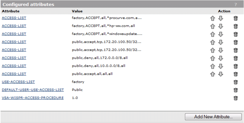
Figure 19
Remaining items to document:
Add information about “IP Helper-Address 172.20.100.22” for each Wireless VLAN (200 and 210) and Active Directory DHCP server (document here) (add this info above by switch configuration)
You can also download this article in PDF format :S1T – HP MSM Wireless Setup-Rev0_4H


